Module 7
[Void Cut by IFC]
If you have ever had to import an IFC model into Revit, you may have realised that the imported model is read only, you can’t do a whole lot with the actual elements. This can be a problem if you need to use the IFC to make changes to the Revit model, such as creating openings for projects with high LOD requirements. Module 7 has been designed to solve this specific problem by demonstrating how a structural IFC model can be used to create openings in walls where the two intersect. Naturally, this workflow could be adapted to suite related situations where openings need to be provided for services such as mechanical, electrical or plumping.
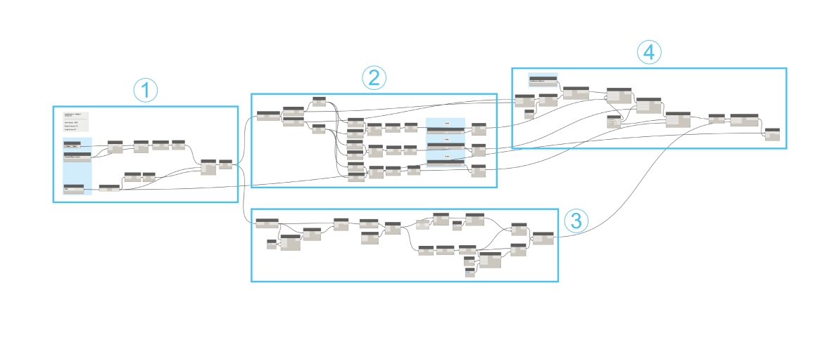
If you are following along with the dynamo file which can be downloaded at the bottom of the page, the order that I will be running through the script is outlined in the image below.Unfortunately I have not included the Void family used as I’m sure it would not work with the different versions of Revit you may be using. It’s a pretty straight forward family to create though and a few details are outlined in the module on how to do so. If you have any questions or suggestions regarding the script, please don’t hesitate to let me know!


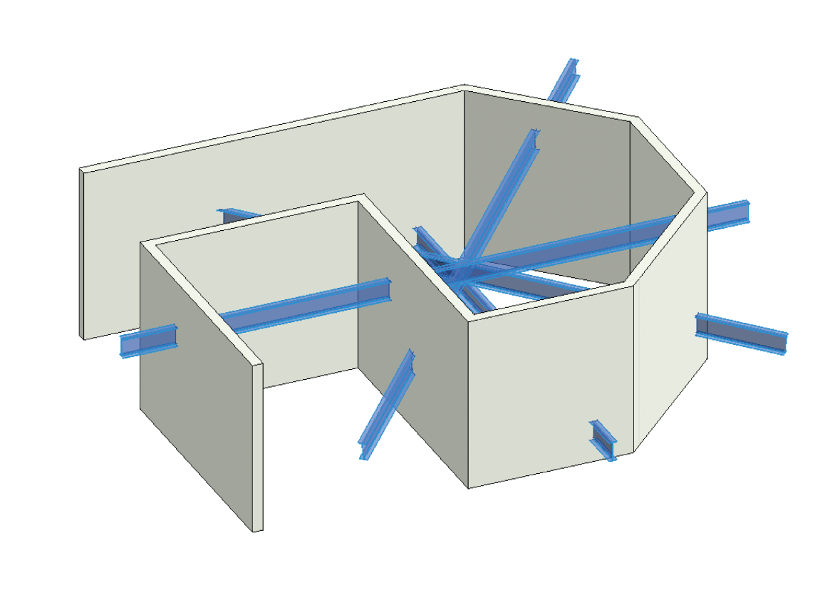
The first section of this script starts off with a few Python Script nodes to filter out the two elements that will be intersecting between the Revit and IFC file shown in the image below. Here in part 1 we first need to select the element category from the IFC file that will be used to find intersections. In this case we are selecting Structural Beam Systems with the Categories node which is fed into a Python Script in part 2. A Boolean node is also used to reset the workflow if needed. This is fed into a Python Script which will be used to first select the linked IFC file we need. The details of this are shown in part 1.1 below.

The output of part 1 is the linked IFC file we will use. In this example I only have one linked file but it would be no surprise if your project uses multiple linked files. So, if this was the case, you would normally need an additional GetItemAtIndex node to fetch the Linked file required from part 1 which is why I have seperated out the two python scripts. As we only have one IFC file, here we can feed the ouput of part 1 directly into the other Python Script file, along with the Categories output from part 1. This Python Script node will filter the input linked file for the category in the secondary input. In this case, all the Structural Beam Systems in the IFC file will be retrieved. The Element.Geometry node is then used to get the beams as a solid and the resulting list is flattened to remove sublists using Flatten.

Once we have the IFC solids, we also need to retrieve the elements that we want to check for intersections within the Revit file. In this case, the Categories node is used to select Walls. All Elements of Category retrieves the elements of this category of which the solid geometry is retrieved and flattened using Element.Geometry and Flatten nodes. The wall elements will also be used later in the script as walls.

We now have two lists containing the solids of the IFC beams and Revit walls. Both of these are fed into another Python Script node which will get the intersections of these two solids as a separate solid. The details of this node is outlined below in part 4.1. The resulting solids are then flattened with the Flatten node.


To start we simply set the only input IN[0] to the variable toggle which is a boolean switch and create an empty list lst. If toggle is set to True then the script runs as normal.

We use FilteredElementCollector to filter the document (doc) of the class RevitLinkInstance as elements. Basically, this filter will retrieve all Linked instances in the Revit file. The output (OUT) is then set to the first item in the collector (coll) of which GetLinkDocument is called to get the instance as a link document. If toggle is set to False, a simple string is output.


After we have retrieved the linked document in part 1.1, this second python script filters the linked document of the category specified in part 1. I have separated the two python scripts as the first script may output several linked documents which can get selected individually. In this case, there is only one linked document so this is input and unwrapped in IN[0] and set to the variable link. The second input (IN[1]) is the category we wish to filter for. To do this, we set up an ElementCatgoryFilter using the category ID which is then applied to a new FilteredElementCollector of the linked document (link). This is done by using the WherePasses method with the new filter (fil) as the parameter. WhereElementIsNotElementType is also used on the collector to retrieve only elements that are not element types.


As we have two lists of solid beams and walls, we can use these to find the solid intersection of the two which is what this script does. We start by getting the current document (doc) and inputs of beam solids (linkedSolids) and wall solids (wallSols) as lists. An empty list is also created as lst which will be the ouput list.

Next we create a for loop through the linkedSolids list containing the beam solids. For each item in this list, we create another for loop through the wallSols list containing the wall solids. By doing this, we can check if each wall solid (j) intersects (DoesIntersect) with the beam solid (j). If they do intersect, the boolean result is set to intcheck. By creating two for loops, we can check every beam with every other wall.

If the intersection result is True, we can then get the solid intersection between the two elements using the Intersect method using the wall (j) and beam (i). This is then appended to the output list (lst).


The output of part 4 contains a flattened list of intersection solids. We can use this to set parameters for the void which will cut the walls for the beams. We begin this process by getting the bounding box of the intersection solids with Element.BoundingBox and retrieve the BoundingBox.MinPoint and BoundingBox.MaxPoint from the resulting list. These lists of points are then flattened with flatten to remove sublists.

With the max points and min points of the bounding boxes, we can get the width, depth and heights of the intersections. To do this, all the Point.X, Point.Y and Point.Z values are obtained and compared with the subtraction (–) node which will show the differences between the max and min points. Math.Round is then used to get the differences as whole numbers and the lists are flattened.

The differences in the max and min points of the bounding boxes are now stored as lists which can be used as the void family depth, width and height. With these values, we can use a Number Slider node and an Addition (+) node to add on to these values if we need the void bigger or smaller. So, we can specify here if we need a 50mm void cut around the beams, for example.


Despite retrieving the bounding boxes of the intersection solids, we don’t have the direction of the beams as the bounding boxes are not aligned to the geometry but rather to world coordinate system of the Revit file. This is because the bounding box node doesn’t work as expected but will hopefully be fixed sometime soon. So, in order to orientate the void family in the same direction of the IFC element, we will need to do a little Dynamoing. First, we need to explode the intersection solids using Geometry.Explode. This gives us a list of surfaces that make up the beam solid. We need to figure out which of these surfaces is the base of the beam so Surface.PointAtParamer and the parameters 0.5 gets us the centroid point of each surface. Using these points and Surface.NormalAtPoint, we can get the normal vector of the surfaces at the centroid which, is the perpendicular vector to the surface. Each normal vector on the beam surfaces should be pointing in different directions.

Using the exploded surfaces and the normal vectors of each surface, we can determine which of the surfaces is the underside of the beam using a Python Script. The details of this script are outlined in part 9.1. It should be noted that this technique of retrieving the base surfaces may differ depending on the type of objects in the IFC. Give me a shout if you need help adapting this script to other IFC files here.

The output from part 9 should be a list of the base surfaces from the beam intersections. We can use these to get their perimeter curves with Surface.PerimeterCurves and then pull them onto a common base plane at origin 0,0,0. This is done with Curve.PullOntoPlane and Plane.ByOriginNormal as the plane input. We do this so we can use these curves to calculate their angle on an XY plane. The image below shows this process with the curves drawn on a common plane.

For each of the curve perimeters, we need to get one common side. To do this, we can use List.Map with List.FirstItem as the function (f(x)) input. What this does is basically apply List.FirstItem to each sublist in the list from part 10. So , we are retrieving the first curve for each of the perimeter curves retrieved from each intersection solid. With this curve, Curve.PointAtParameter is used with the param input as 0.5 to create a point at the center point of each curve. This will be used later to create a vector aligned with the beam.

With the curves retrieved from part 10, we also need to get the center point for a point of reference for vectors in part 13. To do this, we first use Curve.StartPoint to get the start point of each curve and then use these on Polygon.ByPoints to create a single polygon based on the original curves. With these polygons, we can determine the center points with Polygon.Center. Using this point, we can create another point using Geometry.Translate which copies the point and moves it in the Vector.YAxis as specified, by 1000 units. This creates a reference for the world coordinate system of the project in which the void family will be placed.

With the points created in parts 11 and 12, we can create vectors based on the angle of the beam and the YAxis of the project coordinate system. This is done using the Vector.ByTwoPoints node. The start point for both vectors will be the center point of the polygons created in part 12 and the end points will be the single perimeter curves from part 11 and translated points from part 12. We can now determine the angle of the beams in relation to the project coordinate system by using Vector.AngleWithVector. This will be used in the final section to rotate the void families in line with the IFC beams.


To find the underside of the solid beam elements, we can compare the surface height and its normal vector at its center to do the trick. First we store the incoming surfaces (IN[0]) and vectors (IN[1]) to the variables surfaces and vectLines respectively and create an empty output list (lst). These inputs are not unwrapped as we don’t need to use them with the Revit API.

We then start a for loop to cycle through both incoming lists at the same time by using the zip function. At the start of each of these loops we also need to create a variable hi and lowsurf which is empty. The hi variable is intentionally high as it will be used to store the height of the lowest surface. This may need to be increased if your project is very high or using small units.

The variables i and j contain the current sublist of the loop through the surfaces and vectLines lists. So, we need to create another for loop which will loop through each item in these sublists at the same time. Therefore, another zip function is used to loop through each surface (surf) and vector (vect) in the lists i and j.
In each loop, we first get the center point on the surf by calling PointAtParameter with the parameters 0.5 for U and V. The Z-value of this point is then retrieved by using p.Z. With the vector item, we first convert it to a Revit type using ToXyz() and then get its Z-value by checking the vectors property vect.Z.

From part 9.3, we now how the Z-value of the surfaces center point (pZ) and the Z-value of its normal vector (vZ). So, we can use pZ to determine the surface height and vZ to determine its perpendicular direction. To do this, we create an if statement to check if pZ is lower than hi and vZ is lower than -0.1 which will tell us if the normal vector is pointing down in the project coordinates. The reason for this is because in some occasions, the base of the beam may not always be the lowest depending on how it cuts through the wall. If both conditions are true, hi becomes the pZ value and lowSurf is set to the current surface. By setting hi to the pZ value, we can be sure that hi will always contain the lowest Z-value that fits the vZ condition. The base surface of each beam in the loop is appended to lst which is output. We now have a list of the base surface for each beam intersection.


So far we have determined the parameters of the voids we will create and the angles to which they need to align, it’s about time we actually placed them. To do this, we first need placement points. These are created by first using Line.ByStartPointEndPoint with the bounding box max and min points found in part 5 as the parameters. We can then get the midpoint of these lines with Curve.PointAtParameter and 0.5 as the parameter.The resulting point will be the center of the bounding box where our void families will be placed.

After selecting the VoidFamily by using Family Types node, we can place the families with FamilyInstance.ByPoint node using the points from part 14. As stated in the intro, I haven’t included the void family in the downloads but as you can see from the image below… it isn’t too difficult to recreate. An important part to note though, when creating the void family, is that Cut with Voids When Loaded is selected in the family properties.

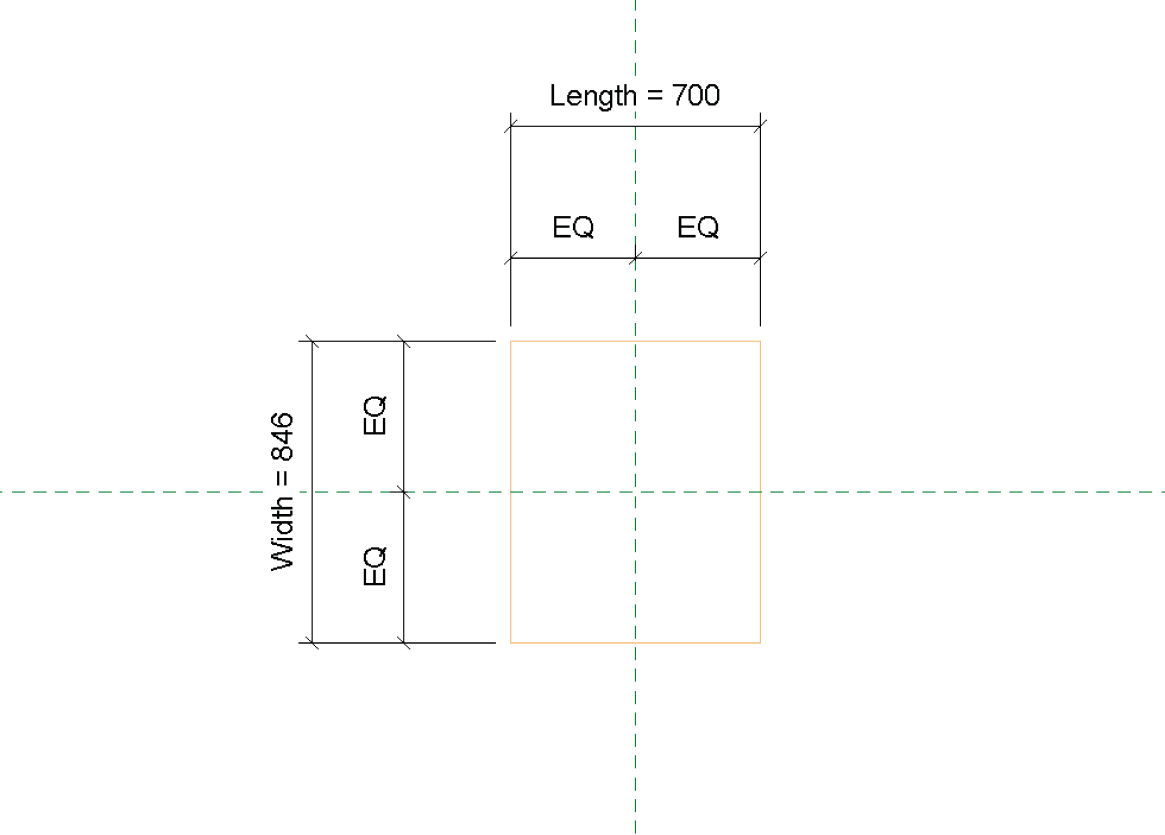
With the void families placed, we need to ensure they are set to the correct dimensions around the beam. This is done using the Element.SetParameterByName node and the string parameters “Width”, “Length” and “Height. These parameters are set up in the void family. The values obtained from the bounding boxes in part 7 can be used here to set the families parameters. Notice that each parameter is set one after other in sequential order. This order doesn’t really matter but they do need to be set sequentially.

Once all the parameters have been set for the void families, the Transaction.End node is used to ensure these have been set before they are rotated. FamilyInstance.SetRotation is used once the transaction ends which which will rotate the void families by the angles derived in part 13 which will align the families with the beams direction. These void families are then fed into the Python Script node along with the wall elements from part 3. This Python Script will cut the voids from the walls which is described in more detail in part 17.1.


To start the incoming walls (IN[0]) and void families (IN[1]) are set to eletocut and voids respectively and an empty list (lst) created. We then create a for loop to cycle through each wall (i) and then another loop to cycle through each void (j). This is so we can compare every void with each wall.

Within each loop through the void families, we try to cut the void from the wall. This is done by first starting a transaction in Revit and calling the InstanceVoidCutUtils.AddInstanceVoidCut using the document (doc), wall (i) and void (j) as the parameters. If the cut is succesful, “ok” is added to the output list and the transaction ends.

If the cut cannot occur , then the script will move to the except section here and “Oops” will be added to the output list. The current loop is then passed (pass) and the next item in the loop starts.
The result of the final Python Script should be a series of voids cut through the input walls where they are intersected by the IFC beams. These voids should all be aligned with the beams, or whatever element you are using, so that the voids cut through only the area that the IFC model intersects with the walls. Obviously this cut can be adjusted to suit how much of a void you want to cut around the IFC element. The gif below is a little example of how this should look/work. The structural beams are an IFC model which cut through the walls at various angles.
Getting the underside of the beams is quite unique for this example so you may need to adjust to suit your needs. Please don’t hesitate to give me a shout if you need any help in doing so. The download files are below so feel free to give them a whirl. If you need to contact me, please leave a message below, contact me via the About page or tweet me @LearnDynamo. There will be many more modules coming up soon too so please subscribe below to get them first.

August 14, 2016 @ 12:33 pm
Hi Jeremy,
very impressive workflow. Thank you for your effort.
Importing of IFC in Revit is not the best act of Revit. User-defined Parameters will not be imported. Do u think a Dynamo script can optimize the importing of IFC??
i hope you can conider such workflow in future post.
thank you again
August 25, 2016 @ 10:05 am
Thanks mate!
That certainly sounds like something I will need to investigate in the future, not sure if it’s possible at the moment. Will have to fix that though!
Cheers
September 20, 2016 @ 12:35 pm
Hi Jeremy,
I’m learning the Module 7 in Dynamo. But when I create the generic model wall base family for VOID FAMILY, the module 7 have some problem and not working. Could you please share the void family for me?
My email: phamthanhhungks@gmail.com
Thank you very much.
Hung
September 23, 2016 @ 5:51 am
Hi Hung,
I think the problem might be the family, it doesn’t need to be wall based, just a generic model. I will send family in any case.
cheers,
Jeremy.
July 25, 2018 @ 8:18 am
Hello Jeremy,
thanks for your awesome example!
I downloaded your script and I tried to use it, but I had the problem that the VoidInstance doesn’t get a level in Revit.
So I tried to use family instance. ByPointsAndLevel instead of family instance. ByPoints but it didn’t work. Then I tried to code it in Python (public Autodesk. Revit. DB. FamilyInstance NewFamilyInstance) giving the level but it didn’t work either.
Is it possible to place a VoidInstance in a Script and assign a level as well? Cause if it is not possible the workflow is in a way not completely efficient.
Thanks in advance!
August 2, 2018 @ 12:13 pm
Hey Ignacio, thanks for your message i’m happy to hear you like the module! I don’t think the void cut does have a level in Revit as it is not an Element.
January 25, 2019 @ 10:36 am
hi Jeremy
I’m learning the Module 7 in Dynamo, and have some problem and not working. Could you please share the void family for me?
Thank you very much. anders
January 30, 2019 @ 9:52 am
Sure thing, send us an email at Jeremy@learndynamo.com and I will send through
February 11, 2020 @ 7:55 am
Hi Jeremy,
I try to learn about Dynamo module 7 and have some error when i load it.
error start at polygon.byPoint, error warning message “Polygon.Bypoints operation failed. You must supply more than two point to create a polygon”
any Idea? by the way I’m using Revit 2019 and already created a void family (generic model-instance parameter)
Thanks,
Denz
May 12, 2023 @ 12:42 pm
Hi Jeremy, I am trying do get the workflow but the link is not working: Did something happened to it?
November 8, 2024 @ 2:53 pm
pp37wf