Module 11
[Room Elevation by Curve]
Ever since I put up Module 2, I have received a few requests for help adapting the module to automatic internal elevations. While I’m more than happy to help anyone that reaches out, I thought it might be easier just to add another module that does just this; create internal elevations by room. This will be part 1 of a few modules to come that will automate the process of creating room elevations, placing them on sheets and adding various annotations.
While creating this module, there was quite a bit of repeat code from Module 2. Therefore, instead of copy pasting text from Module 2, I have wrapped up the process of placing and rotating the views into a node named View.ElevationbyCurve. You can find this node in the Juggernaught package from the package manager. This node will place an elevation at the midpoint of the input curve, with the elevation view facing the normal of the curve direction vector. If you have any issues with this node, please give me a yell and I will be happy to assist.
Part of this script also factors in multiple view family types of the same name. It may be that you don’t have this in your project file so feel free to cut this part out if you don’t need. As always, if you adapt it to anything cool, let me know as I’ll be interested to see! Enjoy.


To start, we need to collect all the rooms in the project that we want to elevate. In this project file, we are elevating every room so the Categories nodes is used to select the Rooms category, and this is fed into a All Elements of Category node. With all rooms, the Room.FinishBoundary and Room.Height nodes are used to extract each room’s boundary curves and height respectively. The height output won’t be needed until section 7. For now, the curves are all that is needed to set up the elevation positions and orientation.

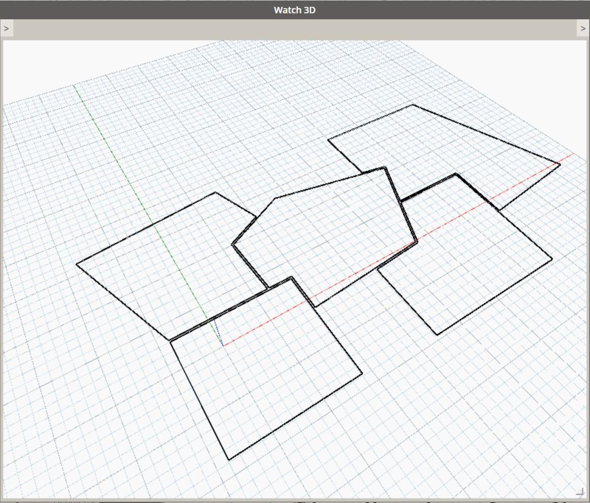
The room boundary curves output from the Room.FinishBoundary node are currently in 4 layers of lists. As we only need a list of curves which belong to each room individually, the Flatten node is used to remove one of the list layers. We then input this into a Python Script node which will smooth the curves. This is done as rooms with multiple walls butting into it, will result in a room boundary which is segmented. So a wall boundary line that appears as one straight line, may actually be segmented into more than one, depending how many walls are joined to it. The details of the Python Script node itself is shown in section 2.1. We can also see the output of this Python Script in the Watch 3D node below which, shows the smoothed polyline for each room.

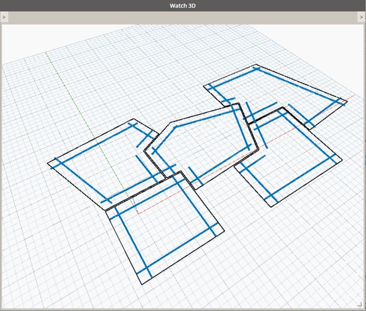
Once the we have the smoothed boundary lines, we need to offset them to set the location of the Elevation markers. To do this we need to set the direction that we want to offset the curve in, which we want to be perpendicular to the wall internally. So, by first reversing the curve with the Curve.Reverse node, we can use the Line.Direction node to get the wall direction and with this, calculate the cross product with the Vector.Cross node and the Vector.ZAxis. By reversing the curve, the cross product will be inward of the room. The resulting vector is then used to translate the wall curves using the Geometry.Translate node and the offset distance of 1.5. Keep in mind here that the offset distance needs to be decent or the elevations might act a bit weird as they are being placed too close to the wall. I would no go much below 1.5 or you may have issues. In the Watch 3D node below, we can see how the lines in blue are offset inward of the rooms.

As we now have the lines to position the Elevations, we need the View Family Type that the new elevation will inherit. To do this, we first need to select the ViewFamilyType using the Element Types node. All elements of this type are then retrieved using the All Elements of Type node. To find the specific view type we want, the names of each are retrieved using the Element.Name node, and the result is checked with the Equals(==) node and the string name we are looking for, this will depend on the name of the elevation view type in your project file. In this instance, I am looking for the view types named Sketch. The output of the Equals node is a list of True/False values which we can use with the List.FilterByBoolMask and original list of ViewFamilyType Elements to filter for the ones we want.

Depending on how your project files are set up, you may have multiple view family types with the same name. For example, a plan view type and an elevation view type both named Sketch type. So, this section will further filter out the type we actually need, that is, the elevation type. To do this, we need to first input the filtered view types into a Python Script node to extract the System Family Name of the View Types which native Dynamo nodes don’t do, as far as I know. The details of the Python Script are shown in section 5.1. With the view type names, we can then use the Equals node again to find the Elevation type. This will output a True/False list which we can use List.FirstIndexOf to find the first item of True type. With this index number, the List.GetItemAtIndex node can be used to retrieve the view family type we want from the original filtered list from section 4.

With our fancy view family type, we can now create the views. To do this, we are essentially doing the same process as i walked through in Module 2, therefore, I have wrapped most of this process up in a custom node named View.ElevationByCurve from the Juggernaught Package. This node takes 4 inputs, a curve which the node will use to create a view at the midpoint facing in the normal vector direction of the curve direction, a viewfamilytype which is used to determine the view type, a viewplan which is the plan view that the elevation marker is placed and RevitOwned which takes a boolean. The default for this last input is False which means the output elements are Dynamo owned rather than Revit owned. If the output are Revit Owned, the element link to Dynamo will be lost once they are created. The output of this node will be an elevation View and Marker which will be facing the room walls.

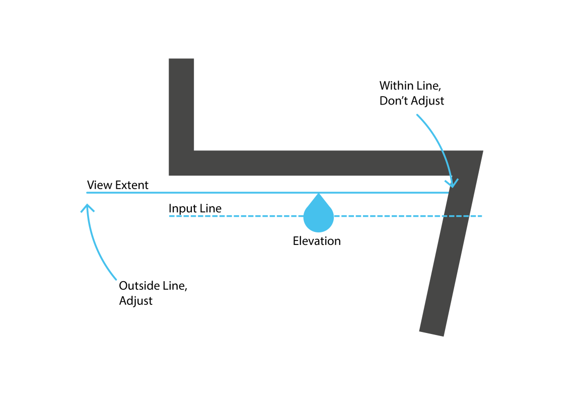
Once we have created the elevation views, they need a little bit of adjusting. This is because the View.ElevationByCurve node will place elevations like we would by hand, the extents will be suited to where they are placed. Therefore, we want to adjust them to be bound to the wall they are facing. To do this we need to use a Python Script node which will adjust the view crops of the elevations. To do this, we can use the same curves we used to create the elevations. If the place elevation extent is large on one side in relation to the curve then we want to adjust it, if it is not, then we want to leave it. This allows us to adjust the elevation extents that are beyond the wall, and leave the extent if it hits an acutely angled wall. The diagram below explains this a little better. The inputs for this node is the curves we used to create the elevations from section 3, the views we just created and room heights from section 1 for inputs IN[0], IN[1] and IN[2] respectively. The details of this Python Script are shown in section 7.1.


After all the usual imports are imported into the script, the curve inputs are stored under the curveLists variable and a new list is created using the output variable which will later append our smoothed curves to.

Next, we need to define a function that will test the direction of two curves so we can smooth them into one curve. To do this, using the def keyword we create a function named checkCurves with parameters named curve1 and curve2. Next we need to normalize the direction vectors of both curves by first getting the curve Direction and then using the Normalized() method, storing the result under the v1 and v2 variables. This will make it simpler to compare the two vectors. Using an if statement, the Vector.IsAlmostEqual is used to check if both curve directions are the same. If so, a new line is created with the StartPoint of curve2 and EndPoint of curve1 which is stored under the newLine variable. If the vectors are equal, this newLine is returned and if not, curve1 is returned. The function will soon be used to check all the curves in our input curves.

With our function ready, we can start looping through the input list of curves. As we have input 3 layers of lists, we need to nest for loops to loop over each curve. The first for loop will loop over each list containing a list of curves for each room. So for each room, we create a count variable storing 0 and setup a temporary list named newCurves. We then start another for loop which will loop over each curve in the list of curves.

With each loop through the list of curves, an if statement first checks if count is equal to 0 and if so, append the curve in the loop to the newCurves list. If count is not 0, the checkCurves function we created earlier is used with the current curve in the loop as curve1 parameter and the last item in the newCurves list for curve2. The result of this is stored under the newCurve variable. This is basically checking if the curve in the current loop is in the same direction as the curve before it, combine them.

The curve which is returned from the checkCurves function is then either a combined curve or the curve1 input as the curves must not be equal in direction. So, an if statement here checks if the newCurve is equal to curve and if so it must be unique and is appended to the newCurves list. If it is not equal then the curves have been combined and we can replace the last curve in the newCurves list with newCurve. This is done by index the last item in the newCurves list, the number for the last item is retrieved by getting the length of the list (len) and subtracting 1. At the end of the loop, the count variable is then incremented.

After we have looped through all the curves and combined all the curves in the same direction, we need to check the first and last curves in our newCurves list as these weren’t checked in the loop. To do that, Vector.IsAlmostEqualTo is used again with the first curve in newCurves as the first parameter and last curve as the second parameter. If these are equal, a new line is created using Line.ByStartPointEndPoint using the points of the input curves and stored under newCurve. The last item of the newCurves list is then removed using the pop() method and our newCurve replaces the first item in the newCurves list.

Lastly, the list of newCurves is appended to the output list and this list is then assigned to OUT after the outer loop finishes.


This simple little script is needed as I can’t find any native nodes that return the System Family Name of the view family types. Therefore, I need to extract the property from the Revit API. To do this, the input elements are unwrapped and assigned to viewFamilyTypes. For every viewFamilyType, we then append to our output list the FamilyName of each type. Simple as that.


This script is needed to adjust the view crops of each elevation so they are suited to the wall they are elevating. To start, all of inputs are stored under curves, views and heights variables, with the views being unwrapped to work with the Revit API. Next we create our empty output list and the revit document is retrieved and assigned to the doc variable.

Using the document(doc), we get then use the GetUnits() method to get the revit project file units class. From this, we can then get the Length units displayed in the Revit project file. In the project file I am using, this is metres. The result of this is stored under getDisplayUnits which will later be used to convert units to the correct type.

Next we need to start a for loop which will loop through each of the curve, views, and heights lists concurrently by using the zip function. Keep in mind the height list is single where as the curves and views lists are nested lists containing the curves and views for each room. So, the height is used once here to convert from internal units to display units by using the ConvertFromInternalUnits method from the UnitUtils class to convert from feet to metres. This is because the room height node used in section 1 returns feet where as we are working in metres. Once we have converted the height variable, we then create a temporary list named tempList which will be used to append our views to later.

We then need to create another for loop which will loop through each curve and view in the curveList and viewList that we are already looping through. This loop is looping through each of the curves and views associated with each room. So, we first need to get the crop region of each view using GetCropRegionShapeManager() and assign it to the viewCropManager variable. Once we have the crop manager, we can retrieve the shape using GetCropShape and the 0 index. We then need to convert this to Dynamo geometry by using list comprehension to loop through each of the crop shape curves and using ToProtoType() to convert them. List comprehension is essentially writing out a for loop in one line. The ToProtoType is the function that is executed for each line (x) in cLoop.

The crop region shape, as you can probably imagine, is a rectangle. Therefore, by extracting the base curve, we can compare it to our input curves and adjust the views. To do this, here we need to get the EndPoint and StartPoint of the curve at index 3 in cLoopCurves and assign them to PointA and PointD respectively. The base curve is at index 3 as the crop region rectangles start at the curve on the left and are sequenced in a clockwise order. Next we can get the midpoint of the base curve by using PointAtParameter with curve and the parameter 0.5, assigning the result to curveMP.

Here is where we compare the base curve of the elevation crop and the curve we used to set up the elevation in section 3 then adjust accordingly. The aim is to reduce any crop base curve that extends further than the input curve on each side, or leave it if not. So to do this, we check if the DistanceTo the midepoint (curveMP) and the curve Endpoint is less than(<) the DistanceTo the midpoint (curveMP) and PointA, then PointA is reassigned to the input curve EndPoint. This same process is then done with the curve StartPoint and PointD. The diagram shown in section 7 might give you a better idea of what this is doing visually. The intent is to crop the sides of the elevation crops to suit the walls but not if the angle of one wall is acute.

Great, so we have now set up two points (PointA + PointD) which we can use to create a new crop region for our elevations. First though, we need two more points which are elevated by the height from PointA and PointD. So we need two more variables, PointB and PointC, and to these we assign two new points ByCoordinates using the PointA and PointD XYZ values with the height of the room being added to the Z value.

Now we can create the lines to form the new crop regions. We can do this with the ByStartPointEndPoint method from the Line class. The order needs to be sequential starting from the left side of the rectangle and going clockwise. So PointA, PointB,PointC and PointD are used to create the lines in this order and assigned to the LineA, LineB, LineC and LineD variables. ToRevitType() is also used on each line to convert the Dynamo geometry to Revit geometry so we can create the new crop region.

In order to assign a new crop region to a view, we need a Curve Loop, created from the Revit API using the Create method from the CurveLoop class. The parameter for this is a list of curves which make up the curve loop. Lucky for us we can use the lines we created in section 7.8, enclosing them in square brackets ([]) to ensure they are in a list. Keep in mind here the order and direction of the lines need to be correct or an error will be invoked.

To assign our new curve loop, we first need to start a Revit transaction using the EnsureInTransaction method and the document (doc) as the parameter. We then set the crop shape of the view using the View Crop Manager we retrieved in section 7.4 and the method SetCropShape with the curveLoop we created in section 7.9 as the parameter. After the method has finished, we end the Revit transaction with the TransactionTaskDone() method.

To assign our new curve loop, we first need to start a Revit transaction using the EnsureInTransaction method and the document (doc) as the parameter. We then set the crop shape of the view using the View Crop Manager we retrieved in section 7.4 and the method SetCropShape with the curveLoop we created in section 7.9 as the parameter. After the method has finished, we end the Revit transaction with the TransactionTaskDone() method.
As you can see from the GIF above, executing the graph will create a series of elevation views directed at the interior walls. These views are then adjusted to suit the walls that they are set off. It’s important to keep in mind how these are created; sometimes you may not get ideal elevations. For example, if you have a wall with a small acute angle, part of the elevation adjacent to this wall will be cut off in the view, depending on where the marker is set. In this case, I would have a long hard think about why you have such small angles in your design or, try setting the marker a little closer to the offset wall.
As I stated earlier, the only issue I found with the graph is that the elevation markers will go a bit nuts if they are set too close to the wall. This makes sense as a marker placed too close to a wall might get confused about which wall it is pointing at. If you do find any other issues though, please let me know as I will be happy to address.
Hope this graph helps you with work and if not, hopefully you’ve learnt a little more about Dynamo and Python Scripting. I will soon be posting a follow up module which starts to place these views on sheets, automating the monotonous parts of work even further so please subscribe below and stayed tuned! If you need to get in touch, you can contact me at Jeremy@LearnDynamo.com or @LearnDynamo on Twitter. If you have any Module ideas I will be happy to hear them too!

November 30, 2017 @ 6:03 pm
Yes, i tried it! It works fine! Also you did a good explanation of your work. Thanks!
December 1, 2017 @ 7:45 pm
Thank you Edgars! I’m glad you enjoyed it.
December 10, 2017 @ 10:45 pm
Awesome work. Have been trying to solve this one for a while.
January 15, 2018 @ 10:19 pm
My pleasure mate
December 21, 2017 @ 10:44 am
Hi,
I am using Revit 2017 and I can’t find ViewFamilyType Sketch. I guess it might be something new in Revit 2018. Is there a way to get this to work without the Sketch ViewFaimlyType?
January 15, 2018 @ 10:22 pm
Hey Simon,
The Sketch type is simply a ViewFamilyType that I have created in Revit and renamed to Sketch. If you Download the associated Revit file above, this will have the type already in the file. Or, you could adjust the Sketch name to whatever name you are using in your Revit file.
Hope this helps!
January 17, 2018 @ 3:28 am
Jeremy thanks for the amazing script.
Is it possible to change the python script to get elevation name from associated wall parameter?
and, also Is there a way to flip this elevation on the other side of the wall to get elevation on both sides of the wall?
Thanks again for the script. Waiting for your response.
January 22, 2018 @ 11:04 am
Hi Karthik,
Thank you, I’m glad you find it useful!
In the script above, to get the wall element associated with the room boundary can be a little tricky. You will have to access the room boundary curves which are used to create the elevations and get the associated element which the boundary was created from… This post from Jeremy Tammik should help..
http://thebuildingcoder.typepad.com/blog/2009/01/room-and-wall-adjacency.html
To flip the elevations to the other side, you will need to offset the boundary curves to the other side of the wall and flip the curves.. this should create elevations facing the wall exterior.
January 17, 2018 @ 6:36 am
I am getting this error for View.ElevationByCurve node “Warning: Node of type ‘View.ElevationByCurve’ (D:\AppData\Roaming\Dynamo\Dynamo Revit\1.3\packages\Juggernaught\bin\JuggernaughtRevit.dll) cannot be resolved” Please help me
January 22, 2018 @ 11:06 am
Hi Kevin,
Thanks for your message and sorry to hear that isn’t working! Can you try removing and reinstalling the Juggernaught packaging and see if that helps? If not and it’s no trouble, can you send me the files you are trying to use it on?
my email is Jeremy@learndynamo.com
cheers!
February 1, 2018 @ 4:20 pm
Same problem here.
I’ve tried uninstalling and installing again but no joy. I’m using Revit 2017.2 and Dynamo 1.3.2.
PS Nice script BTW and thanks for sharing! (even it’s not working for me :P)
February 13, 2018 @ 9:16 am
thanks mate!
mmmm, sorry to hear it’s not working for you though.
Can you please send me a picture of what data you are inputting?
cheers,
Jeremy
November 20, 2019 @ 11:50 pm
Hi, I have the same problem. Its not anything to do with inputting. For some reason our computers arnt reading the dll file in package manager. Do you have the .dyf of the node we can download?
November 20, 2019 @ 11:58 pm
I think its if your storing your package on a server
January 25, 2018 @ 6:25 am
I am getting this warning on the first python script.
“Warning: IronPythonEvaluator.EvaluateIronPythonScript operation failed.
Traceback (most recent call last):
File “”, line 28, in
File “”, line 13, in checkCurves
AttributeError: ‘Arc’ object has no attribute ‘Direction'”
I got it to work with small project. but its not working for a big project and have curved rooms fyi.
I am using Revit 2016 and Dynamo 1.3.
Could please help me with this thanks in advance.
January 31, 2018 @ 10:07 pm
Hi Karthik,
You are having that problem because the Arc object does not have the Direction property, which is throwing an error…
I haven’t really factored in curved walls in this workflow. You could possibly fix by skipping over arcs when cleaning the curves but then i’m not sure how the elevations will go with arcs. It will require a bit of rework. When I get some time I will have a look at solving that one!
August 3, 2018 @ 12:12 pm
Unless you’re going to try and unroll the elevation somehow, you might try turning the arc into a series of facets and elevate each one separately.
January 30, 2018 @ 3:16 am
Jeremy thanks for the script I have few issues with this script whenever wall is curved or if wall has a profile the script wont run.
It would be great
I posted this in Dynamobim forums
https://forum.dynamobim.com/t/elevation-by-curve-module-11-room-finish-issues/18610
January 31, 2018 @ 10:07 pm
Hey mate, see my reply above.
February 6, 2018 @ 10:07 pm
This is absolutely awesome! Thank-you!!!
Just for future reference.. we set the number slider to 1000 to offset the required distance in mm.
Now off to rename views acording to location….
February 13, 2018 @ 9:14 am
Thanks Lauren, happy to hear you are using it!
Thanks for the pointer, glad to hear it still works.
Good luck and let me know if you get it going 🙂
April 16, 2018 @ 12:51 am
Hey Jeremy
Great work! Your tutorials are by far the most indepth and easy to follow so thanks for sharing with us.
I can’t seem to see the view.elevation.bycurve node in your latest Juggernaught package. Do you know if its still there?
I’ve tried to adapt the script from your module two in place of the missing node and can get it to create the elevations and markers…but the last step of
adjusting the view extents is throwing me out.
April 20, 2018 @ 9:40 pm
Thanks Andy!
I’ve heard a few people have had that problem so I am going to re-release juggernaut to fix. Sorry about the errors!
With Dynamo 2.0 out now, that package will have a few changes.
cheers,
Jeremy
May 16, 2018 @ 4:39 am
HI Jeremy,
This looks great but i am receiving an error message at the first Python Script node (2.1 – 2.7)
Warning: IronPythonEvaluator.EvaluateIronPythonScript operation failed.
Traceback (most recent call last):
File “”, line 24, in
TypeError: iteration over non-sequence of type Line
I am also having issues with the “List.GetItemAtIndex” node as well
Warning: List.GetItemAtIndex operation failed.
Index was out of range. Must be non-negative and less than the size of the collection.
Parameter name: index
Any advice on what the issue might be?
I am using Revit 2016 with Dynamo 1.3
Any help appreciated
May 17, 2018 @ 4:27 pm
Drew,
For your iteration error on line 24, you don’t have enough list depth. Need to be at the second level in lists. I had a similar issue with how I modified the script.
May 22, 2018 @ 10:59 pm
Thanks Scott.
Scott is right, it is trying to loop over a line basically, not a list. I think i created this before list levels was introduced so needs to be modified for that.
The List Item error is because there is no item at the index specified i.e. the list is not long enough for the index.
Let’s me know if you need a hand.
Jeremy
August 9, 2018 @ 9:46 am
Hi Jeremy,
Thanks a lot for this, I’m trying to adjust the graph to make elevation views from the faces of Masses, to assist with early stage feasibility work.
I take the base surface of the Mass, extract the perimeter curves and plug this into your Curve Reverse and Geometry Translate nodes (I’ve also got a notional 9m view height). It works great apart from the crop region fails, with the error message:
Warning: IronPythonEvaluator.EvaluateIronPythonScript operation failed.
Traceback (most recent call last):
File “”, line 31, in
TypeError: int is not iterable
Would you have any suggestions? I can forward the graphs and files if you wouldn’t mind having a look?
Cheers,
Mark
August 15, 2018 @ 12:17 pm
hey Mark,
No worries mate, I’m glad to hear you are using it!
Is this for the python code in section 7? Are you providing a list of heights or just one height? If it is just one height you will get this error as it needs to be a height for each room (in this module) in a list.
cheers,
Jeremy
August 9, 2018 @ 2:13 pm
Hey Jeremy, I use your Mods a lot, they are supremely helpful. I did want to reach out because I am learning and wanted to have more control of the pointing direction of the elevations. The script works works well in all room and model line cases. When I try it with the scope box, I get one elevation that is pointed in the wrong direction. Where do you suggest I start to modify this part of the code / where to troubleshoot the code.
Thanks! These are really the best tutorials.
August 15, 2018 @ 12:19 pm
Hey Jasmine!
Awesome, great to hear you are learning from them!
If you go to Module 2, that is a more python centric version of this that might be more adaptable. It sounds like the issue might be in the Juggernaught node but most of what that is doing is shown in module 2.
Give me a shout if you need more help.
cheers,
Jeremy
August 16, 2018 @ 4:16 pm
Jeremy
I have arrived here after watching your excellent Lynda.com tutorial this is a truly fantastic resource and I’ll be spending a lot of time here over the next few weeks.
Some time ago I was working on using sections to produce the room elevations as they can be created directly on a line, but this needs changed now I can produce elevations.
The reason for my message is that if you add List.FirstIem set @L3 between Room.FinishBoundary and Flatten it will remove isolated elements like columns from the boundary and stop elevations from being produced from each one.
Many thanks
September 2, 2018 @ 7:54 am
Hi Nick,
Great to hear you enjoyed the course and hope you find learn more from this site!
That’s great to know, thank you for leaving the message! I am going to update many of of these exercises so will keep that in mind.
Cheers!
November 30, 2018 @ 9:20 am
Hi Jeremy,
I’m having an issue with the upper extents of the crop boundary on the views.
It should relate to the room height but it is being multiplied by 304.8. It extends to 1219200 rather than 4000.
304.8 = 12 x 25.4 so I’m assuming it has something to do with the unit conversion?
Regards,
Ger.
January 30, 2019 @ 9:46 am
Hi Ger,
yes most likely a unit conversion error, are you in feet?
February 5, 2019 @ 1:30 pm
Hi Jeremy, thanks for getting back. I’m working in metric. I ended up just dividing the height by 304.8 within the script and I now get the correct crop. Can’t see why it is multiplying it in the first place though.
March 26, 2019 @ 2:49 am
Hi Jeremy,
View.Elevationbycurve is still active ? as i m trying on the script and get Juggernaut pkg 1.1.0 but it’s still shows as unresolved node.
Can you please advise. ? I am using dyn 2.0.2 in rvt 2018 ..
thx
September 23, 2019 @ 5:35 pm
Jeremy,
First off thank you for your sharing of knowledge!
I am unable to locate “View.Elevationbycurve” in the package version 1.1. Have you dpreicated this node or is it an incompatibility with the newer versions and is no longer available.
Thanks.
May 30, 2019 @ 3:04 am
That is quite cool.
Is it possible to have the elevations to view the other way ie from the outside towards inside?
J
July 19, 2019 @ 11:27 am
I see you don’t monetize learndynamo.com, don’t waste your traffic,
you can earn extra cash every month with new monetization method.
This is the best adsense alternative for any type of website (they approve all websites),
for more info simply search in gooogle: murgrabia’s tools
September 23, 2019 @ 5:36 pm
Jeremy,
First off thank you for your sharing of knowledge!
I am unable to locate “View.Elevationbycurve” in the package version 1.1. Have you dpreicated this node or is it an incompatibility with the newer versions and is no longer available.
Thanks.
November 21, 2019 @ 3:09 am
It was working before but for some reason its only make 2 elevations for a room when its inputting lines for 7 elevations. Would you have any advice?
September 17, 2020 @ 7:24 am
Will be chance to see View. ElevationByCurve node on the juggernaut package? I downloaded the 1.1.0 version and it is no longer there. Thank you for your time!
November 21, 2019 @ 10:13 pm
Hey Jeremy, Jeremy here. Awesome Script. I just ran it across 26 rooms across 5 levels. Did pretty well. About 10 elevation views in though it gave up lifting the height of the crop box. Got the error message below. Thanks for your great work
Warning: IronPythonEvaluator.EvaluateIronPythonScript operation failed.
Traceback (most recent call last):
File “”, line 63, in
Exception: Boundary in boundary should represent one closed curve loop without self-intersections, consisting of non-zero length straight lines in a plane parallel to the view plane.
Parameter name: boundary
January 17, 2020 @ 4:48 am
Hi Jeremy,
On Youtube, I saw one person wrote script to create continuous elevations by selecting one model line and put all that continuous elevations in the sheet for presentation. But in the video he never showed for some end script. Please can you help me figure out what will be the lack script in the video? Really appreciate for your effort and help.
https://www.youtube.com/watch?v=k-edvzziLX8
I also attached youtube video link for your reference. Thank you!
April 2, 2020 @ 2:52 pm
Thank you Jeremy for your detail explanation, this is truly helpful and the entire community really appreciated it.
By any chance do you know where is the View. ElevationByCurve node on the juggernaut package? I downloaded the 1.1.0 version and it is no longer there.
Thank you for your time!
September 17, 2020 @ 7:20 am
Will be chance to see View. ElevationByCurve node on the juggernaut package? I downloaded the 1.1.0 version and it is no longer there. Thank you for your time!
March 29, 2021 @ 12:16 pm
Hi.
I am new in Dynamo and I have a problem with Python script 2 :unexpected Token newLine.
Can someone help me.
Thanks a lot
January 27, 2022 @ 8:03 am
Hi Jeremy,
And Happy New Year,
I tried your Dynamo and it worked very well until yesterday. I don’t know if you have deleted the element “View.ElevationByCurve” in the package Juggernaught but Dynamo cannot solved it anymore. Except that, your instructions are very helpfull, thank for all this topic ! Still usefull in 2022 😉
Thanks a lot
January 27, 2022 @ 12:29 pm
You know what guys, i figure it out. If the element in the Revit category (where you find “View.ElevationByCurve”) of the package Juggernaught disappear, it’s because there is an incompatibility between some packages (i don’t know yet which one). Still trying to find out
November 8, 2022 @ 11:54 am
Great Script, Aa quick question here. How to increase the crop offset?
For e.g. I want to see 500mm beyond my view extent. I know how to modify in Revit. But can it be done in the same script?
May 16, 2023 @ 12:25 pm
Hi! I have got an error at the end of the script… The python node says:
AttributeError: unittype [‘File “”, line 29, in \n’]
Do you have any clue on this?
Thanks,
Giorgio
May 16, 2023 @ 12:28 pm
Hi! I have got an error at the end of the script… The Python node says:
AttributeError: UnitType [‘File “string”, line 29, in module \n’]
Do you have any clue about this?
Thanks, Giorgio
December 27, 2023 @ 12:07 pm
the Node View.ElevationBYCurve is not showing in Revit 2022 Dynamo version can you please look in to issue.
rest working fine in 2021