Module 2
[Unwrapped Elevations from Model Line]
Module 2 has been designed to help solve a problem that I frequently run in to, especially when working on large projects with irregular shapes. Basically, it unwraps elevations based on a model line of some sort. This works well for unwrapping large projects like stadiums with multifaceted facades as well as unwrapping interior elevations. It can be used in this way where walls may be linked in from another Revit file in which case elevations will not snap to them.
I have tested the script on just selecting walls and it does work in most cases although not all the time which means some manual alterations may be needed. You will also need to swap out the CurveElement.Cuve node at the start to extract the line location of the wall elements. If you need help doing this, don’t hesitate to give me a shout.
The script was primarily built for model lines although it can be used for any line based family type such as walls so go nuts with it and see what you can do. Also, please feel free to adjust it as you please and let me know if you improve or adapt it to some new function.


Select Model Elements is used to select the model elements in the project file. From these curve elements, CurveElement.Curve allows us to extract the base curve of the element into a usable Dynamo format. This is where you would need to alter the script to suit selecting walls.

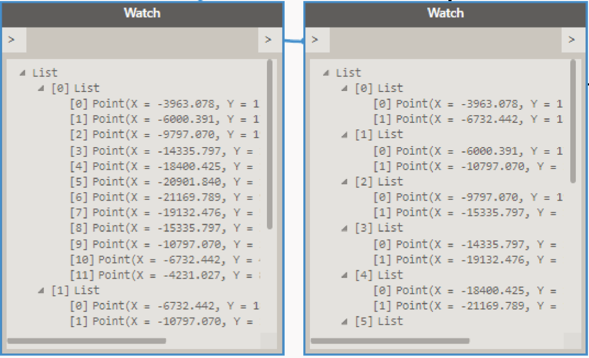
Once we have the curves we need, we can start extraction information from them for the script. StartPoint and CurveEndPoint both do just what they sound like ; get the endpoints of the curves. These points are then combined into a single list using List.Create and the result is transposed using List.Transpose. If you are not familiar with the concept or transpose, it is basically used to interchange the number of rows with the number of columns in a matrix or vice versa. In this case, the list of two sub lists has been transposed into a list of six sub lists based on the original number of items in the first list. This list of points has been transposed to match the number of planes coming out of Plane.XAxiz. This can be seen in the two watch nodes below where the left is before the transform and the right is after.
From the curve elements we also extract a coordinate system using Curve.CoordinateSystemAtParameter. This is set at parameter 0.5 which is the midpoint of the straight line. Using this new coordinate system, we create a plane with Plane.XAxis and convert the coordinate systems to points using Point.ByCartesianCoordinates.

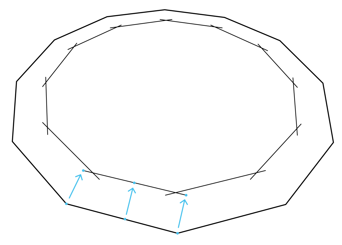
The list of transposed points and planes extracted in part 2 can now be moved or translated using the Translate node. The new planes will be used for the elevation markers and the curve end points will set up the boundary of the crop views. The Number Slider allows us to adjust the location of these points in relation to the model line. Putting this number in the positive or negative spectrum will adjust the marker location to either side of the model line.
A diagram of what is occurring in this section is shown below. This is based on a dodecagon shape made up my model lines.


Using the translated points for the crop view boundary, we once again transpose the list so that we can swap the list back to its original form of 2 items. Once it is in this form List.FirstItem and List.LastItem are used to get all the items from each sub list.
The translated points for the elevation markers will be used later when the elevations are created.

Now that we have all the translated curve endpoints in two separate lists, we can use these to create new lines with the Line.ByStartPointEndPoint. These lines will make up the base of the crop views so Curve.ExtendEnd and Curve.ExtendStart nodes are added so that we can extend the crop view as needed by the value stated in the Code Block.

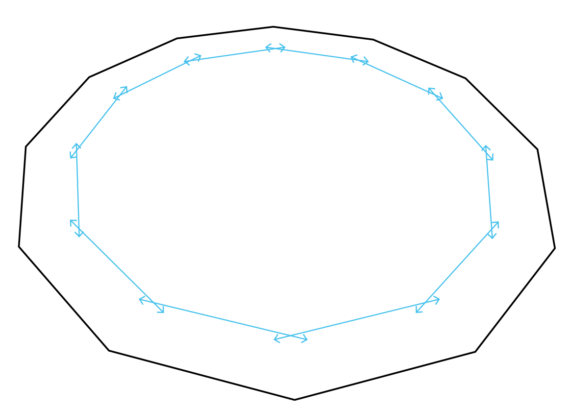
From the extended curves, we once again get the start and end points from Curve.StartPoint and Curve.EndPoint respectively. A list is then made from these and transposed to achieve the same result as shown in part 2 which is the end points of each crop view in their own sub list. This can be seen below in the sample diagram.


Similarly to part 3, the points obtained in part 6 are translated using Geomery.Translate but this time in the Z axis using Vector.ZAxis. This creates the upper corners of the crop views that will be created and are controlled using either Number Slider to move the points up or down.

Both lists from the Geometry.Translate nodes are transposed so that all end points are grouped together and in the same fashion of part 4, we gather up each of the end points using List.FirstItem and List.LastItem. All of these points now form the corners of each crop view that will be created. Therefore, they are grouped together in the List.Create node and in an anti-clockwise order.

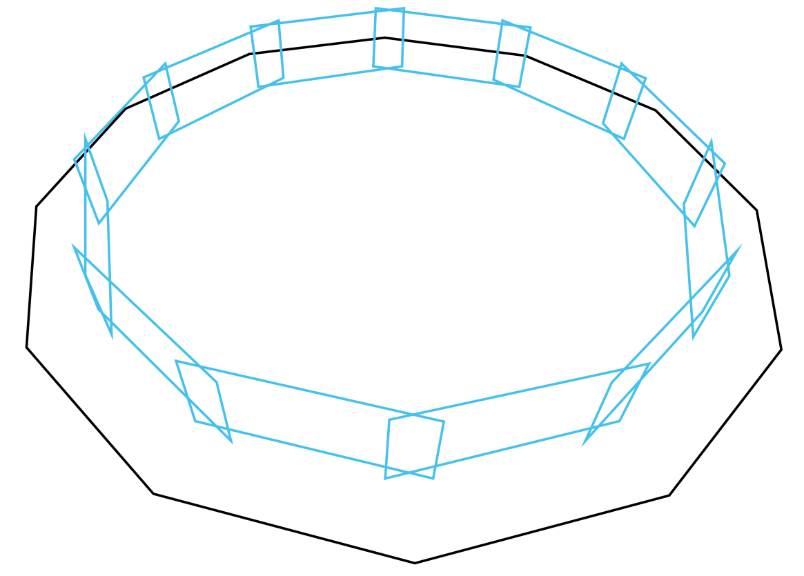
List.Transpose makes a return to separate all these grouped lists into their corresponding crop views so we now have all the points of each crop view in their own sub list. From this, PolyCurve.ByPoints is used to make a loop from each sub list of points. Each curve of these loops are then extracted using PolyCurve.Curves so that they can be used in the following Python Script. The poly curves that have now been created are shown diagrammatically below.


Before we create the elevations, we need to select the ViewFamily Type to use. This Python Script does just that. The details of this are shown below starting at part 10.1 onwards. The output of this script is a list with two sublists, one that contains the ViewFamily Types and the other with their names. With this information, we can use the Code Block node to first select the list of elements using the [0] code and then the number of which element we want to use, in this case the first so another [0] is added.

The final part of this module is completed using a Python Script. I originally thought this would be a simple script but it turned out to be quite large. It’s relatively simple to understand though so please read through to get an understanding of how it works in part 11.1 onwards.


With these Python Scripts I am not going to explain the importing parts as the reason for these are explained in module 1.
To start, 3 empty lists are created under the variables elements, names and lst. These will be the outputs of the script.

A FilteredElementCollector is then used to filter the document (doc) of class ViewFamilyType and the result is set to the variable collector as elements.

With all these elements collected, we loop through them with a for loop. In the first loop, we find View Families of the type Elevation and append it to the elements list. Then another loop is set up to loop through the parameters of this element. Once the loop finds the elements Type Name it appends this to the names list. Finally, both the elements list and names list are appended to the output list; lst.


The incoming data is stored under the corresponding variables. This includes the points where the elevation markers will be created (points), the midpoint of the original model lines (modelPoints), the curves that make up the crop views (cropCurves) and the ViewFamily type chosen in part 10 (viewType).

As shown in module 1, the toggle is set to True to make the script activate. This is so we can refresh the script if needed. We then start a transaction which is needed to create elements within Revit, more information about this can be found here.
We then start a for loop through the points list. The enumerate function is used to get the index of each item in the list. So , we can then get the model line mid-point (modelMP) from the modelPoints list at the same index as the current point in the points list.
ToXyz converts the Dynamo point to Revit type as explained in this link and from this the X and Y values are taken from modelMP.

Each individual curve line is taken from the cropCurves list at the same index as the current point in the points list. Each one of these curves are set to l1, l2, l3 and l4.

The current elevation marker point is set to elevationPT. This is used to make another point (elptRotate) which is located 100 units above elevationPT in the Z axis and both points are used to make a line set to ln. This line will be used as the axis for elevation marker rotation.

In this part, the X and Y values are taken from the elevationPT point and with these values, we subtract the modelMP X and Y values that we extracted earlier. These new values are then used to perform an atan2 function which gets us the angle between both points. This angle will be used to rotate the elevation marker towards the model line.

With all the information gathered, we can now create an elevation marker using the document (doc), view type (viewType.Id), location point (elevationPT) and scale of view (100). An elevation is then created at that marker and set to variable ele.
The elevation marker is then rotated to be pointing at the wall using ElementTransformUtils.RotateElement(Document, element ID, rotation axis, angle).

The crop region manager is set to crManager and then we gather the curves brought in earlier to form a new curve loop which is then set to cLoop.

Finally, we try to set the crop region of the elevation to the new curve loop using SetCropRegionShape and hopefully it is successful!
If the python script is successful then we should have a group of newly formed elevations show up in revit, all pointing towards the model line at the side set. The crop region should also be set as per the parameters in parts 3 and 7 for length and height respectively.
An example of how this should appear can be seen below. If you come across any problems, please let me know but hopefully that isn’t the case. Also, if there is anything I haven’t fully explained or you do not fully understand please give me a shout via email or in the comments below. In addition to these, if you liked the script and want more, please follow me on twitter @LearnDynamo and subscribe to the emailing list below for the next module release.


May 16, 2016 @ 7:42 am
Fantastic! Worked first time. I don’t think I’ve ever gotten someone else’s graph to work without some tweaks, or having to download packages.
A question: in step 3 there is one slider feeding both ‘Elevation Crop Boundary’ and ‘Elevation Marker Point’. I assume ‘Elevation Crop Boundary’ is where the elevation cut line is, and ‘Elevation Marker Point’ is where the reference is placed. I tried feeding a different value into ‘Elevation Marker Point’ but it makes no difference, both cut line and marker are placed at the same point.
Am I misunderstanding something here? (the reason I tried it is I want the cut line close, which puts the reference on top of what is being elevated).
Some useful enhancements would be to be able to control what the elevations are named and a more intuitive way to select the elevation type (by name for example). I can probably work out the latter, but I couldn’t see any way to name elevations.
And the ultimate – avoid having to draw lines by creating an elevation by selecting an object, or objects, by using their boundingbox.
May 18, 2016 @ 12:04 am
G’day Antony!
Awesome to hear it’s working for you mate! I’ve tried to reduce the use of packages so people get a better understanding of how the script works.
I’ve just tried what you are describing and I got the same issue which isn’t ideal. Placing elevations are trickier than one would think so I believe it’s happening due to the relationship between the marker and cut line. One possible way around it would be to use the bounding box to define the outline rather than the crop view although that’s another module in itself.. I will look in to it though and see what I can come up with to help with this problem. Thanks for pointing it out!
That’s a good point, I’m certainly going to look at that for future revisions so thanks for the feedback.
Your last point is interesting too… I didn’t consider that but it’s certainly possible…
May 20, 2016 @ 12:52 pm
Is there anywhere you can download this graph, or at least the Python script, as I’m sure to make a syntax error if i try typing it all in myself
May 20, 2016 @ 2:33 pm
Hey Phil,
Of course mate, just above us, there is a blue file icon, that text below it is the link to download the file, enjoy 🙂
May 25, 2016 @ 6:46 pm
I made a modification to your script that uses room boundaries to generate elevations, I am running into an issue with the elevations. The elevations seem to only generate up to a certain point. Do you happen to know any reason why it does that? I am trying to troubleshoot it currently an dam interested in seeing your thoughts on this problem.
May 31, 2016 @ 3:42 am
I’m not sure I completely follow John, drop me an email via the About page and I’ll see what I can do to help.
June 24, 2016 @ 6:36 pm
Thank you Jeremy! That’s very helpful!
But I have an problem at step 10/3 when editing the python script. I got a warning saying:
File “”, line 35, in
AttributeError: ‘NoneType’ object has no attribute ‘Definition’
Do you know what might be the reason?
Thank you in advance!
June 24, 2016 @ 6:45 pm
Never mind now. It is because of the typos. Oops…
June 25, 2016 @ 12:58 am
Glad you sorted it 🙂
October 23, 2016 @ 9:43 pm
Shuqi,
I was wondering if you can share the scrpt with me. Isee to be getting the error mentioned in you’re post and have checked it over and is correct!
July 28, 2016 @ 11:37 am
Hello, I am trying to work with this for wall elevations. I have tried with your script as it is, and by adding Revit model lines on the boundaries of each room. The problem is in the first (top) geometry translate node where I am getting null values (input types not matching).
Alternatively, I am trying the room boundaries to generate the lines. I extracted the curves and exploded the geometry, feeding the ‘Curve.StartPoint’ and ‘Curve.EndPoint’. Everything goes well until I reach ‘List.FirstItem’ and ‘List.LastItem’, both listing/containing polycurves. Then I tried exploding the polycurves, flatten them (now with curves’ starting and ending points) and then feeding ‘Line.ByStartPointEndPoint’. The input types do not match, so I got up to this point.
Any guess on what is wrong?
July 29, 2016 @ 3:17 am
Hey Francisco,
It’s a little hard to figure out what’s going wrong without looking at the workspace. If you can email me at Jeremy@learndynamo.com I will be happy to take a closer look at your problem and help out.
August 9, 2016 @ 6:41 pm
Hey Jeremy awesome script. Is this script meant to respond to only one enclosure. Like you have one dodecagon (1 room). I am trying to get the script to run once for multiple rooms. I seem to be having issues. I don’t know if it because the unwrap elements lines in the python script area dealing with elements in one list whereas i have lists of lists (as in multiple model lines per room, with 22 rooms in total).
I was able to generate the model line from the room boundary curves and have it generated based on the name of the room. Please, I will send the script for you to look at. Will save a lot of time as I’m sure you know.
Thanks.
August 10, 2016 @ 8:17 am
Hey mate, cheers, I’m glad you like! Sounds like that could be the case, you would need to flatten the list of element lines before feeding them into the Python script. If you send me the file I will be happy to have a look.
August 19, 2016 @ 7:58 pm
I have modified your setup to select walls/storefronts, but i’m getting an error in the final python script saying that the ‘Point’ object has no attribute “ToXyz”, would you happen to know why i’m getting this error?
August 25, 2016 @ 10:09 am
hmmm, that method is unwrapping a Dynamo element to be used with Revit API… are you using Revit 2017?
March 4, 2017 @ 8:17 pm
same problem here
http://imgur.com/lJ49fvd
any solution so far?
March 4, 2017 @ 8:24 pm
missing clr.ImportExtensions(Revit.GeometryConversion)
April 11, 2017 @ 12:43 pm
Hi Damian S
I got the same problem but i can’t sole this. Have you try to figure it out?
TL.
May 31, 2017 @ 4:53 pm
Hi Jeremy,
I am fighting with the same problem “object has no attribute “ToXyz””, I am not sure how to solve this… I have imported “clr.ImportExtensions(Revit.GeometryConversion)” as specified in the link provided in the post but it does not work.
Any idea why? I am using Revit 2016 and Dynamo 1.2.
June 6, 2017 @ 11:40 am
Hey Alberto, do you want to drop me an email with files at Jeremy@Learndynamo.com and I will have a look. Cheers
August 23, 2016 @ 8:14 pm
Does this work for Revit 2017? I’m getting an error:
“Warning: IronPythonEvaluator.EvaluateIronPythonScript operation failed.
Traceback (most recent call last):
File “”, line 6, in
IOError: System.IO.IOException: Could not add reference to assembly RevitServices
at IronPython.Runtime.ClrModule.AddReference(CodeContext context, String name)
at IronPython.Runtime.ClrModule.AddReference(CodeContext context, Object reference)
at IronPython.Runtime.ClrModule.AddReference(CodeContext context, Object[] references)
at Microsoft.Scripting.Interpreter.ActionCallInstruction`2.Run(InterpretedFrame frame)
at Microsoft.Scripting.Interpreter.Interpreter.Run(InterpretedFrame frame)
at Microsoft.Scripting.Interpreter.LightLambda.Run4[T0,T1,T2,T3,TRet](T0 arg0, T1 arg1, T2 arg2, T3 arg3)
at System.Dynamic.UpdateDelegates.UpdateAndExecute3[T0,T1,T2,TRet](CallSite site, T0 arg0, T1 arg1, T2 arg2)
at Microsoft.Scripting.Interpreter.DynamicInstruction`4.Run(InterpretedFrame frame)
at Microsoft.Scripting.Interpreter.Interpreter.Run(InterpretedFrame frame)
at Microsoft.Scripting.Interpreter.LightLambda.Run2[T0,T1,TRet](T0 arg0, T1 arg1)
at IronPython.Compiler.PythonScriptCode.RunWorker(CodeContext ctx)
at Microsoft.Scripting.Hosting.ScriptSource.Execute(ScriptScope scope)
at DSIronPython.IronPythonEvaluator.EvaluateIronPythonScript(String code, IList bindingNames, IList bindingValues)”
This is happening on the Python Script node towards the end of the graph
August 25, 2016 @ 10:10 am
Hi,
I haven’t tested with Revit 2017 but will review and update for Revit 2017 + Dynamo 1.1.
thanks for letting me know!
September 22, 2016 @ 11:42 am
Hi Jeremy,
Works perfectly for me! Excellent work.
I was wondering if the far clip offset could be manipulated?
Also the output of the Python node is a string indicating whether or not the elevation was successfully created, it would be nice if the elevations themselves were output as I was hoping to control some of the parameters (such as far clip offset), we have ‘view sub type’ which is used to group within the browser, which would be good if this could also be controlled.
Other than that – excellent work. Definitely saved me (and I imagine everyone who visits) a great deal of time.
September 23, 2016 @ 5:55 am
Hi J-P,
Thanks for the feedback mate!
The far clip offset can be set through editing the BuiltInParameter of the elevation I believe. Its a great idea to output elevation too. I will definitely incorporate both of these suggestions when I revise the module after 1.2 release.
Thanks again mate!
Jeremy.
December 30, 2016 @ 5:40 pm
I made this modification to my script. I then took the views create and renamed them.
staring at line 18:
http://pastebin.com/86508NWX
this output will give you two lists. First list will be how Jeremy had it, second list will be the list of elevations created with element ID values. It will still give the “set run gate to true” if it is false.
January 10, 2017 @ 9:09 am
nice, thanks mate!
November 22, 2016 @ 2:56 pm
Hello Jeremy,
I just found your site and I appreciate the way that you go through your step-by-step explanation process (at least on Module 2, which is my starting point). I have done some modifications to generate a line at the location of a storefront and used that line to create the curve data needed to run through your map. I get to the last script which generates the views and I get the following message:
Warning:
IronPythonEvaluator.EvaluateIronPythonScript operation failed.
Traceback (most recent call last):
File “”, line 50, in
TypeError: ‘PolyCurve’ object is unsubscriptable
I am currently using Revit 2016 with Dynamo Core/Revit 1.2.0.2690
January 10, 2017 @ 9:55 am
Hi Eric,
Glad you like the module, always good to hear feedback.
That error usually happens when trying to use an object as a list or array by calling an index. This might be happening in this case. Is the Python in the last script exactly as i’ve shown above? i.e, is line 50 — ” comby = elevationPT……etc.
Cheers
Jeremy
December 30, 2016 @ 5:47 pm
Jeremy,
I posted above on a comment from J-P about outputting the newly created view id’s. Hopefully this can help save you a few minutes.
R16 Dynamo 1.2.1
I also have a question about the creation of the elevations. I am not seeing a logic behind if it is created from the “inside” or “outside” of the element. Is there a way to force the elevations to create from one side?
Explanation: I have gathered all storefronts in the project, create curves from the storefronts, then input the curves into what you had created. I want all of the storefronts to be elevated from their “outside” as recognized in Revit. Where you designated in Group 3 that you were offsetting the marker a distance, I thought the positive vs negative would handle that but it doesn’t always appear to. Most of the storefronts are elevating front the “outside” but not all of them. I don’t know if flipping them after they are drafted has an effect on this.
Hopefully that makes sense.
January 10, 2017 @ 9:46 am
Hi Scott,
Thanks for the comment.
When I have tested, the value in part 3 indeed changes the marker onto each opposing side. Do you have any screenshots that show your problem?
cheers,
Jeremy
May 18, 2017 @ 4:37 pm
Jeremy,
I finally got around to playing with the script. I should probably share what all I’ve done. Before I do, I want to know if you have ideas of how to fix this bug.
http://imgur.com/a/JkuOP
My script isolates storefronts, then use Element.GetLocation to create the curve. This is where I tie into your script. I set the elevation maker offset to -5.
In the image link above, I drew storefronts based on up to down and left to right because we know how picky revit is. Then rotated and mirrored the storefronts in each direction because you never know how people will make changes or if they truly understand how revit works. Hopefully you can follow my semi-logical grid. You can see which elevations don’t create on the correct side of the wall or face the wrong direction. If the system gets mirrored, it will be on the wrong side every time. Then there’s the goofy drafted wrong direction (up to down) where it always wants to face left.
Is there a way to detect the outside of the wall within python so it knows which face of the wall to aim at?
Let me know your thoughts.
Thanks, Scott
May 28, 2017 @ 10:20 am
Hey mate,
Looks like the elevations are giving you a good run for your money! I’ve noticed the bug you are talking about, before. I haven’t had time to investigate why it’s happening but it sure can be annoying.
As I can recall, when creating views via the API you can’t specify what walls to point the elevation marker at… i’m sure there’s a smart way of doing it and I will update you once I figure it out!
cheers,
Jeremy
May 30, 2017 @ 4:41 pm
They have been but its a going to be worth it when I finish. I figured out using vectors how to determine wall directions and how to change the start and end points of the model lines to get the elevations on the correct side of the wall. I have all of the views on the correct side of the walls! WIN #1.
In 2 particular instances, the elevations away from the wall when created. I created a list with 0’s and 180’s for additional rotation direction. I lack on python skills and maybe this is where you’ll know a quick answer. Lines 61-68 you calculate the angle “ang”. If could add my 0’s and 180’s to your calculated “ang” values it would rotate everything to the right direction.
As soon as I have it done I’ll post for all to see.
Thanks, Scott
February 17, 2017 @ 6:44 am
Hi Jeremy,
I modify your script and generate room elevation. It works well except one thing.
If the generated elevation and wall at sides. the crop region would snap to the wall. And I find the script cannot resize the crop region as expected. The region is resize but nothing can be seen in the new area. Do you have any idea?
February 20, 2017 @ 8:35 pm
Jeremy,
My problem was I was making my test shape with the revit polygon drawing tools. It would then orient my walls in a down/up or left/right direction. So half the walls were indeed facing reverse of how I anticipated.
We are working on upgrading to 2017. I am having an issue with getting the python to read the curves to generate the crop boundaries. It still creates the views but I get the “Missed Elevation” report. Have you noticed a similar problem or determined what change needs made to correct it? I know revit API changed from .Curve to .getCurve when gathering from an unwrapped element. But with the segments already being unwrapped, I don’t know what else would need adjusted.
Thanks – Scott
May 30, 2017 @ 4:39 pm
They have been but its a going to be worth it when I finish. I’ll post some images and links when I’m done.
I figured out using vectors how to determine wall directions and how to change the start and end points of the model lines to get the elevations on the correct side of the wall. I have all of the views on the correct side of the walls! WIN #1.
In 2 particular instances, the elevations away from the wall when created. I created a list with 0’s and 180’s for additional rotation direction. I lack on python skills and maybe this is where you’ll know a quick answer. Lines 61-68 you calculate the angle “ang”. If could add my 0’s and 180’s to your calculated “ang” values it would rotate everything to the right direction.
As soon as I have it down I’ll post for all to see.
Thanks, Scott
February 20, 2017 @ 11:40 pm
Hi Jeremy, great script!
Just a heads up that in Revit 2017 the SetCropRegionShape() method (line 59) has been replaced with SetCropShape()
http://www.revitapidocs.com/2017/new.html
March 3, 2017 @ 8:51 pm
Thanks for the heads up mate, need to update!
March 20, 2017 @ 4:25 pm
Hi Jeremy,
Great script on the creation of elevations in Revit. Also fantasic website. Just had one question regarding the script, please excuse me if you have already answered the question.
I was looking to add a feature of selecting view templates, Would this operation have to be carried out through the Python scripting?
Lee
March 21, 2017 @ 10:42 pm
Hey Lee,
Thanks mate, glad you like it and appreciate the feedback.
In answer to your question, you could do this in Python by changing the ViewTemplateId property in the views that you are creating. Let me know if you need a hand doing so.
Cheers
May 16, 2017 @ 10:58 pm
Home run! Great sligugng with that answer!
March 30, 2017 @ 8:47 am
Hi Jeremy,
Big thanks for this awesome website, you are doing a great work and helping a lot of people like me.
I am studying your scripts in depth to learn python and it is been very useful so far, but I am stuck in the Step 10.3. line 36. Using http://www.revitapidocs.com I managed to figure out that “Name” is a Property of the Definition Class and gives you “The user visible name for the parameter”. Therefore you call the parameter names of the family with the statement j.Definition.Name to compare with the exact parameter name “Type Name”. But how do you know that the name of the parameter is exactly “Type Name” and not “TypeName” or just “Type”… where can I check the actual name of the parameters? Sometimes they differ from how they are shown in Revit. For this example, the type name appears in Revit as just “Type” when you open the Type Properties window of any family.
Many thanks in advance,
Angel
April 3, 2017 @ 11:39 am
Hi Angel,
Thanks mate, I appreciate the feedback and glad to hear you are following along!
A good way of finding the information you are after is to download Jeremy Tammik’s addin for Revit; RevitLookUp. You can download it here: https://github.com/jeremytammik/RevitLookup
This will let you view Elements properties and relationships, very handy to quickly look at parameters.
Let me know if you need a hand setting it up.
cheers,
Jeremy
April 21, 2017 @ 2:30 pm
Many thanks Jeremy!
I will get RevitLookUp installed and will let you know if I need a hand.
Best,
Angel.
August 1, 2017 @ 1:07 am
Hi Jeremy,
Thank your script, that is a very great idea and rule to create elevation and rotate . I try to change the dynamo to create elevation by select the room element. But I met a problem. When the angle is 180 deg the python always give the same answer like 360 deg. I have no idea why happen this,
Thank again.
Markus
August 1, 2017 @ 3:24 am
I found rule to fix the python, I try to change the python program like this:
ang = atan2(combY, combX)/2
ang1 = atan2(combY, combX)/2
#Create elevation marker and elevation in position 0.
eleMarker = ElevationMarker.CreateElevationMarker(doc, viewType.Id, elevationPT, 100)
ele = eleMarker.CreateElevation(doc, doc.ActiveView.Id , 0)
#Rotate elevation marker towars model line.
ElementTransformUtils.RotateElement(doc, eleMarker.Id, ln, ang)
ElementTransformUtils.RotateElement(doc, eleMarker.Id, ln, ang1)
I try to use twice rotate to change the elevation angle, this may not a great rule , but it can be get the right answer. I don’t know why , I hope you can give me a answer, thank again.
August 1, 2017 @ 11:49 am
Hi Markus,
Thanks mate, I’m glad you are enjoying it!
I have definitely come across that problem before and am also stumped as to why it happens. When a view is rotated close to 180 degrees, it adds a further 180. However, I have since solved the issue by checking the direction of the view and if it is facing in the wrong direction, changing the position of the view in the marker.
I am close to posting another module that shows how to create room elevations based on rooms, hopefully that helps!
cheers,
Jeremy
August 10, 2017 @ 1:43 pm
How come you are so brilliant Jeremy!!!
Always so quick to rely!
You are a Jem!
November 27, 2017 @ 3:40 pm
Hi Jeremy,
Your script is great and helping me alot.
I just wondering if I do anything wrong since I can adjust my elevation range.
Elevation range seems to be fixed by room even when I change boundary extension (5) or upper and lower extend (7).
I am using Revit 2017 and Dynamo 1.3.
Thanks in advance.
January 24, 2018 @ 10:56 am
Hi Dzung,
I think this is an issue with how the Revit API places elevations and their boundaries. Try working with the updated Juggernaught node in Module 11, it might be a bit easier for you.
cheers
January 23, 2018 @ 3:52 pm
I am trying to get this script to work for walls, and I was reading everyone’s comments and I am still having troubles. I am using 2018.2. Any guidance would be well appreciated.
January 24, 2018 @ 10:54 am
Hi Brad
Check out Module 11, it is an improvement on this script and will work better with walls.
August 29, 2018 @ 11:42 pm
Hi Jeremy,
Thanks a bunch for creating this site and providing these examples. I am just barely getting started and was trying to recreate your script but when I copy and paste your code into an empty python node I get an error message? If I copy and paste the node from your *.dyn file it works fine. Any ideas what is going on?
September 2, 2018 @ 7:37 am
Thanks Daniel, i’m glad to hear you are enjoying it!
That’s odd, what is the error?
September 8, 2018 @ 9:50 pm
Thanks for sharing!
Is there any way to create an Interior Elevation instead of Building Elevation. I have a feeling this needs to be done in the python script but I could not figure out which lines to alter. Please let me know if you have an insight on how to do this.
Thanks so much,
David
January 30, 2019 @ 9:41 am
Hey David,
Yes it should be achievable, have you had a look at the output from step 10, this is retrieving elevation views, look for the interior view and retrieve that before inputting to final node
December 18, 2018 @ 9:24 am
Hey!Jeremy,
In the second script, I don’t understand the 11.2, could you be more elaborate?
January 30, 2019 @ 9:42 am
Hey Bimbang, which line specifically do you not understand?
January 22, 2019 @ 3:01 pm
Hi, Jeremy
Thank you so much for this amazing script !! I have really been struggling for days to create elevations properly. But now I’m on the next step and I really need your help 🙂 I tested it on regular model\draft lines and everything works perfectly
I’m trying to use the script with the room collector script from lunchbox in order to get interior\exterior elevations of rooms. The only problem is that one out of the four generated elevations is facing the wrong direction, and it is always the right sided one. It only happens when the wall to the right of the room is in a 90-degree angle and no matter where I place the elevation marker offset (using the slider) it always looks to the left.
I removed the “Select Model Elements” node and added the room collector node and a flatten.list node instead.
Ideas?
January 30, 2019 @ 9:43 am
Hey Yahya, seems odd, have you tried switching the direction of the room curve?
February 6, 2019 @ 9:11 am
Dear Jeremy
thanks for the amazing tutorial, I was trying the script but sadly I got this error below, I hope you have time to take look at it,
have a nice day
Warning: Plane.XAxis expects argument type(s) (Autodesk.DesignScript.Geometry.Plane), but was called with (Autodesk.DesignScript.Geometry.CoordinateSystem[]).
June 26, 2019 @ 6:41 pm
Hello, I have the same issue. Did you find a solution ?
July 29, 2019 @ 2:30 pm
Same issue here…
November 20, 2019 @ 2:30 pm
Same here, anybody got a solution?
November 20, 2019 @ 2:47 pm
I used the CoordinateSystem.XYPlane node and my script worked
March 18, 2020 @ 1:33 pm
Thank you, Marty_1
March 15, 2019 @ 3:46 am
Hello,
I followed your wonderful class on Lynda. Nice explanations: you take care of creating new variables anytime that make things simpler than other coursed I followed on the subject. Congratulations. Maybe we even met at TokyoAU University last Octob
I am with Revit2019 and Dynamo 2.02.
I am posting regarding the View.ElevationByCurve node which I assume is under revision as I have not found. therefore I got back to module 2 and I tried to updating myself.
Over there I kept error on line 66 Warning: IronPythonEvaluator.EvaluateIronPythonScript operation failed.
Traceback (most recent call last):
File “”, line 66, in
AttributeError: ‘type’ object has no attribute ‘CreateBound’ line
but on the REVIT API HELP it says the method is there
March 18, 2019 @ 4:11 am
Hello Jeremy,
sorry to bother you again.
I solved the previous problem, just using the full description for Line, Autodesk.Revit.DB.Line which is weird anyway [from Autodesk.Revit.DB import * is there].
Now I do not get why the short node (10) to collect views – only the Elevation ones – does not collect anything from the active file therefore
does not feed anything to the main Python scripts…I am wonder if there is a way to use the Taskdialog instruction to check where the script fail to debug it that you may suggest.
thanks,
June 15, 2019 @ 1:53 pm
Hi there mates, its fantastic post regarding teachingand entirely defined, keep it up all the
time.
December 30, 2019 @ 7:10 am
Hi Jeremy,
I also tried to create same node and scripts as you do but I have not received any result. Please would you like to help me solve this issue?
Hope to hear good news asap Jeremy.
with best regards,
PSA
January 6, 2020 @ 2:18 pm
Has anyone sorted the “ToXyz” Issue? Thanks
January 9, 2020 @ 7:57 pm
I am also facing with same issue for “ToXyz”. Is anyone can solve for us. Thanks!
January 20, 2020 @ 2:47 am
I like composing textual essays (such as post!).
March 18, 2020 @ 1:23 pm
I am using revit 2020 & have warning in Step 2, Plane.XAxis.
Can you help?
March 18, 2020 @ 1:36 pm
Got it – thank you!
April 6, 2020 @ 8:16 pm
Hang cho, May I ask how you fixed it? I have the same problem..
Thank you in advance.
January 30, 2021 @ 3:26 pm
Hello!
First of all, thank you very much Jeremy for the amazing tutorial!!
I had the same problem (have warning in Step 2, Plane.XAxis) and I fixed it like that:
I use the node “CoordinateSystem.XYPlane” between Curve.CoordinateSystemAtParameter and Plane.XAxis.
I hope it helps to someone!
Thanks again!
January 31, 2021 @ 3:58 pm
Hi! I’m again!
I change a couple of things more and now works perfectly!
1.- In the second Python Script (11/8) I replaced SetCropRegionShape for SetCropShape (because that method has been replaced in Revit 2017)
2.- If you are using Revit 2017, meter as unit and metric system…
—- > you should use -2 or -12 in the Number Slider in step 3 (-2 for inside to outside and -12 for outside to inside).
—-> you should use 5 and -1 in the Number Sliders in step 7 (aprox. 5 for Upper Extend of Elevation from F.L. and aprox. -1 for Lower Extent of Elevation from F.L.)
I hope it helps someone! Thank you Jeremy for your amazing work!
December 15, 2021 @ 8:29 pm
Great! Glad you solved it!
April 21, 2021 @ 4:49 am
Hi, thank you for sharing this useful code. Thought I get an error that I do not know how to fix. Could you kindly please guide me how to fix it?
Here is the Link to the error screen shot: https://imgur.com/a/1drU5As
December 15, 2021 @ 8:29 pm
Hi,
This is because a method is being used on a null object, or ‘none’. Make sure there are actual items in the list tat the method is performing on.
September 9, 2021 @ 9:33 am
Hi!
Thank’s for sharing this code.
I’m using dynamo 2.6.
In the second Python script I get this error: AttributeError:’Point’ object has no attribute ‘ToXys’.
Notice that I have changed “Plane.XAxis” whit “CoordinateSystem.XAxis”(2) and I replaced “SetCropRegionShape” with “SetCropShape” (Ines 31.01.2021).
Thank’s.
December 15, 2021 @ 8:28 pm
Hi Alain,
Is it ‘ToXyzs’ exactly because it should be ‘ToXyz’
December 12, 2021 @ 9:20 am
Hi
Thanks for the code
I downloaded your code
No problem when using the single Element selection mode (Select model element)
But when I use multi select elements mode (select model elementS) The final Python gives the following error
***Warning: IronPythonEvaluator.EvaluateIronPythonScript operation failed.
Traceback (most recent call last):
File “”, line 47, in
AttributeError: ‘List[object]’ object has no attribute ‘ToXyz’****
Revit 2021-2022 Dynamo 2.12
I struggled for hours but the problem was not solved
Please advise
December 15, 2021 @ 8:26 pm
Hi SIPBIM,
This is likely happening because you will need to loop through the multiple selected elements. So the method “ToXyz” is being applied to a list of elements and not a single element. Use a for loop to loop through and use that method on each element in the list.
August 4, 2023 @ 10:10 am
Hi, I appreciate this is an old thread, but I’m having similar issues as mentioned previously.
I’ve downloaded the script, and made the following adjustments:
– changed the input so it is using the curves of a room boundary (obtained via a Crumple node)
– Plane.XAxis node changed to CoordinateSystem.XAxis node
but I’m still getting the “no attribute ‘ToXYZ’ error in the second Python Script (line 46).
Apologies, my Python knowledge is a bit too limited to delve too far into this, can anyone offer a solution?
Revit 2023.1
Dynamo 2.16.1
August 30, 2023 @ 8:37 am
I have the same issues about the second Python Script as @Dan
AttributeError:’list’ object has no attribute ‘id’ [‘File””,line53,in\n’]
Revit 2023
DYNAMO v.2.16.1
December 4, 2023 @ 5:20 am
We specialize in inground pool cleaning for
vinyl, fiberglass, and concrete pools.